I got the original idea for this project after watching a video by DIY Perks.
He shows how to extract the backlights of old monitors as well as TVs and explains the effects of the different layers build into them and how they make for a better light source:
I will start after the actual extraction process and explain how I created my own RGBW controller with an ESP32, some buttons, and a small display.
As I'm writing parts of this in retrospect I won't be able to show every step but rather the respective parts.
1. Preparing the backlight
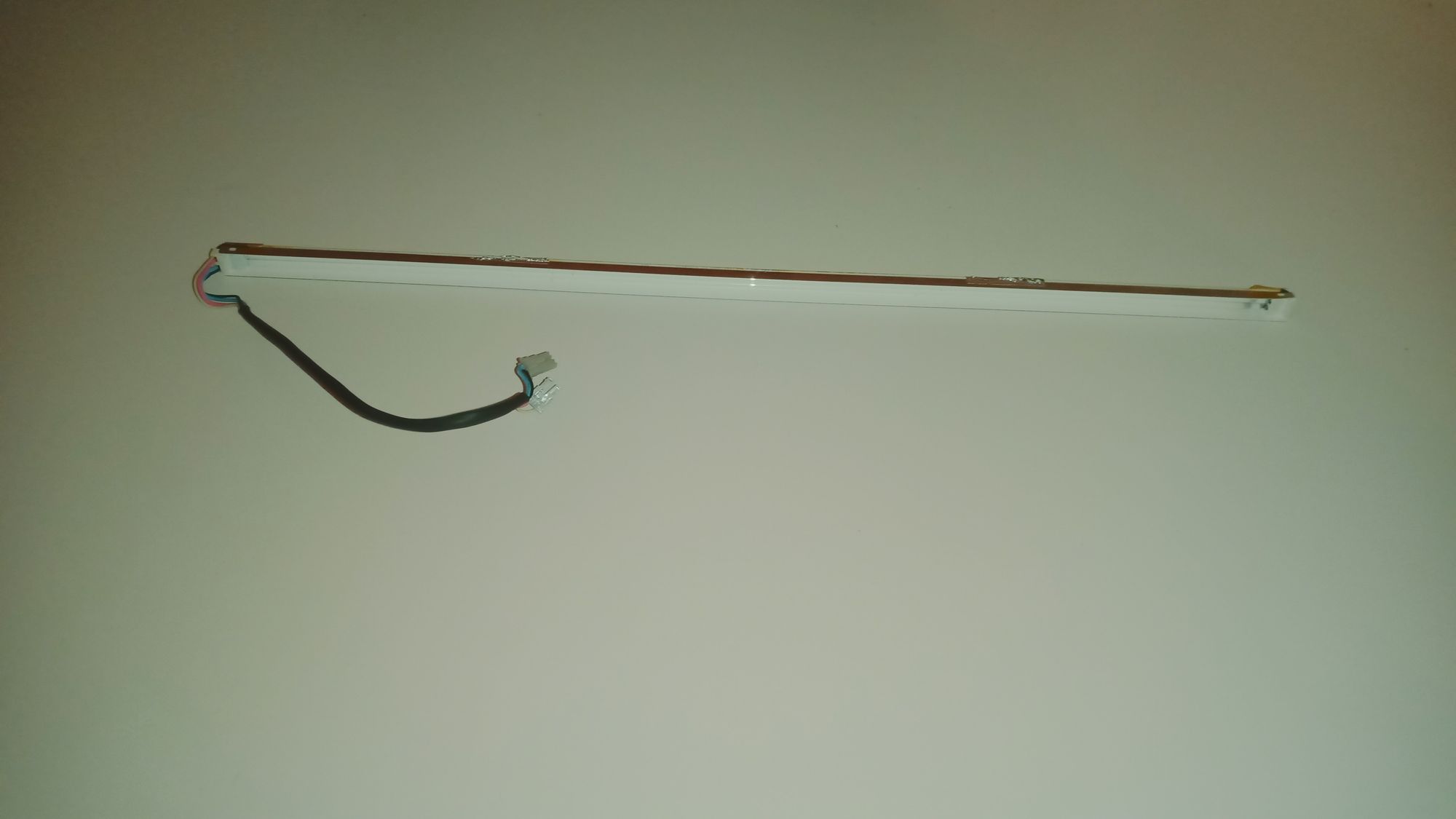
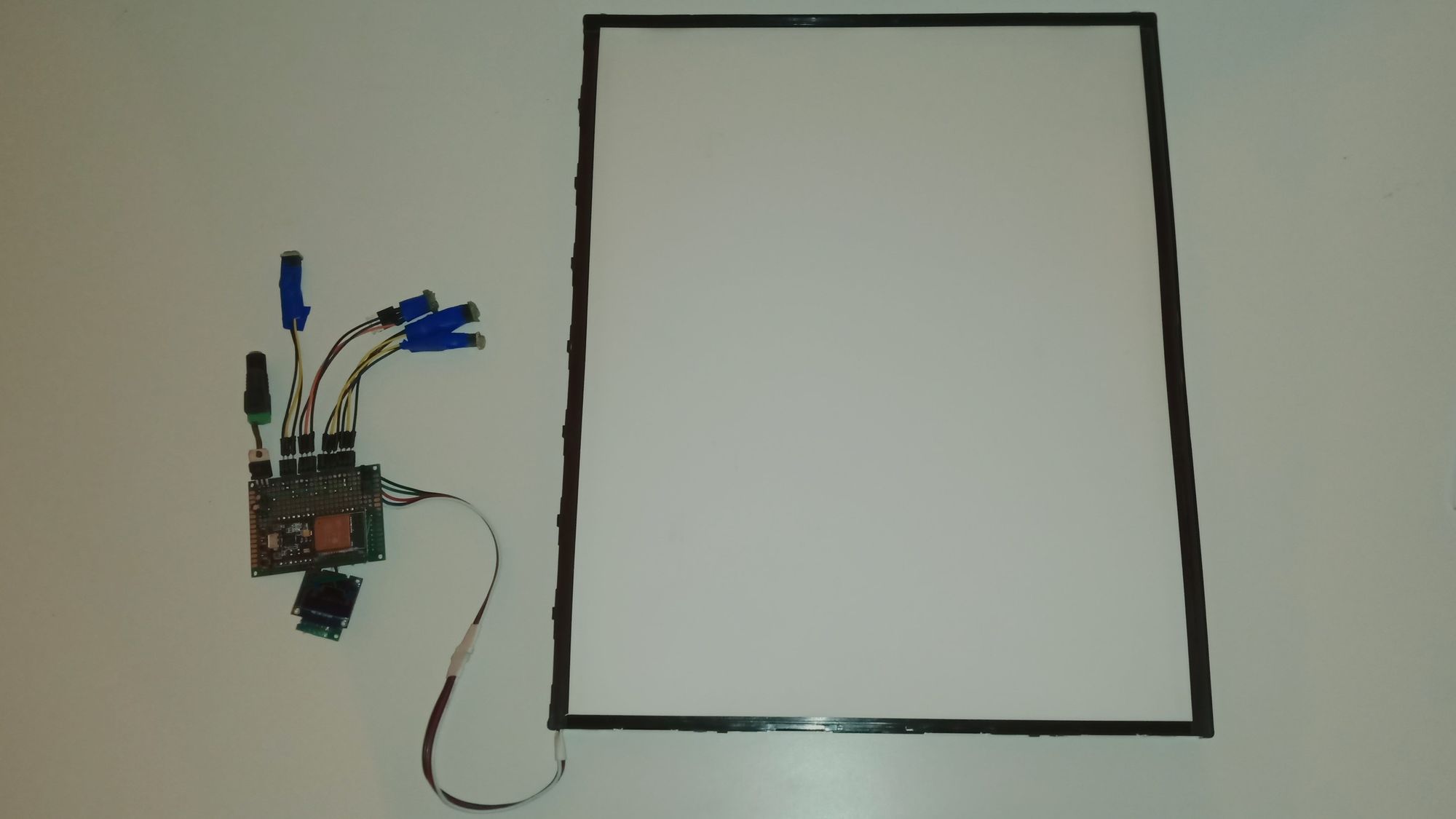
The only thing I did after fully disassembling the backlight was to replace the build-in fluorescent lamps with an RGBW strip.
The strip was split into two and connected with some wires I had lying around. After that, I added some milky plastic in front of the strip for some additional diffusion and assembled the backlight again.
2. Designing the controller
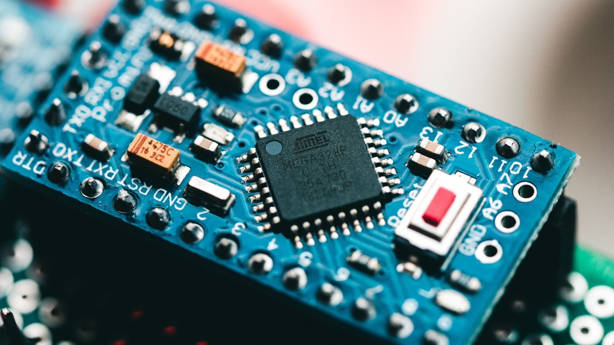
2.1 The microcontroller
For the project, I wanted to prototype fast and without being too concerned about the limitations of the hardware.
That's why the ESP32 was such an easy choice, as it:
- is quite small
- has moderate ram and flash storage
- has integrated WiFi and Bluetooth
- is something I have experience with
- is fast enough for more complicated computations(animations or different color selections for example)
2.2 Choosing an IDE
For a development platform, I deliberately chose against using ArduinoIDE even though I'm using its framework and am experienced with the IDE.
What I did chose is the VSCode integration PlatformIO, which allows to easily build projects for Arduinos, ESPs, and the likes. And as it is integrated into VSC it can leverage all the other integrations and tools build into that.
In addition to that is PlatformIO more friendly for bigger and more structured projects and encourages them, as it's:
- creating a local lib folder for project-specific libraries
- creating a test folder to be used by the PIO unit test framework
- having project configurations in an extra file allowing for multiple devices and environments in the same project
2.3 Deciding on a framework
The last part of the puzzle was deciding on the actual framework to use.
Like I said above I chose Arduino, but let's see what frameworks I looked at and why I decided that way.
I had to decide between the standard Arduino framework that works with almost every microcontroller under the sun and the ESP specific framework ESP-IDF provided by the manufacturer.
The standard Arduino framework has far more libraries than the ESP one, taking away lots of the work needed. ESP-IDF, on the other hand, allows to fully take advantage of all features the ESP provides, without any workarounds and loss of performance.
And while fully utilizing the capabilities of the ESP32 sounded like fun, I wanted to leverage as much of the already existing tools already written for Arduino, for example, the display library I'm using, without having to port everything to work with ESP-IDF.
In addition to that, I already had a lot of experience working with the Arduino framework.
3. Designing the board
3.1 Materials
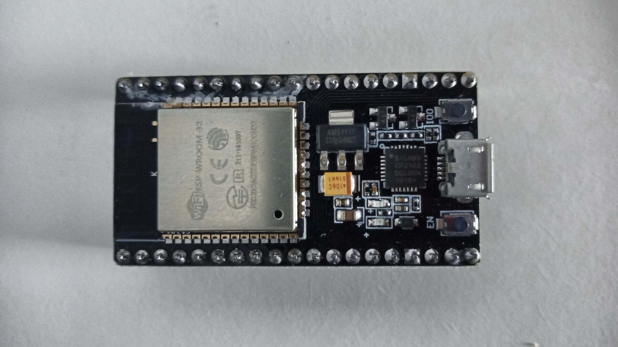
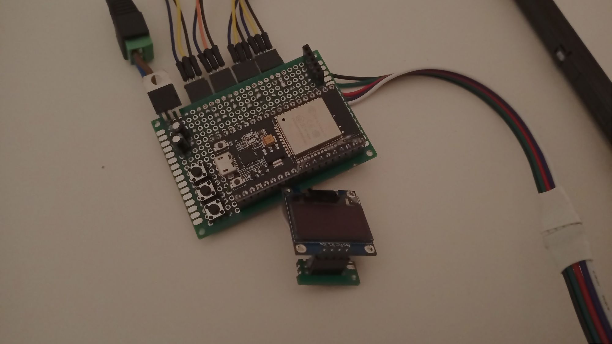
As I did not want to build the additional periphery needed to work with a bare-bone ESP32 I opted for a devboard variant that already included those things and does not need to be surface mounted. And to save myself some headaches I also got some female headers as well to be able to swap out the board should I accidentally kill it, like I inadvertently would(already did.. twice..).
While I originally wanted the controller to be primarily used wirelessly, I soon realized that it would be much better to also have some way to directly interact with the device.
That would allow the device to be much simpler and much more immediate to control as well as allowing me to focus on the basic features of an RGBW controller without having to implement any WiFi or Bluetooth support from the get-go.
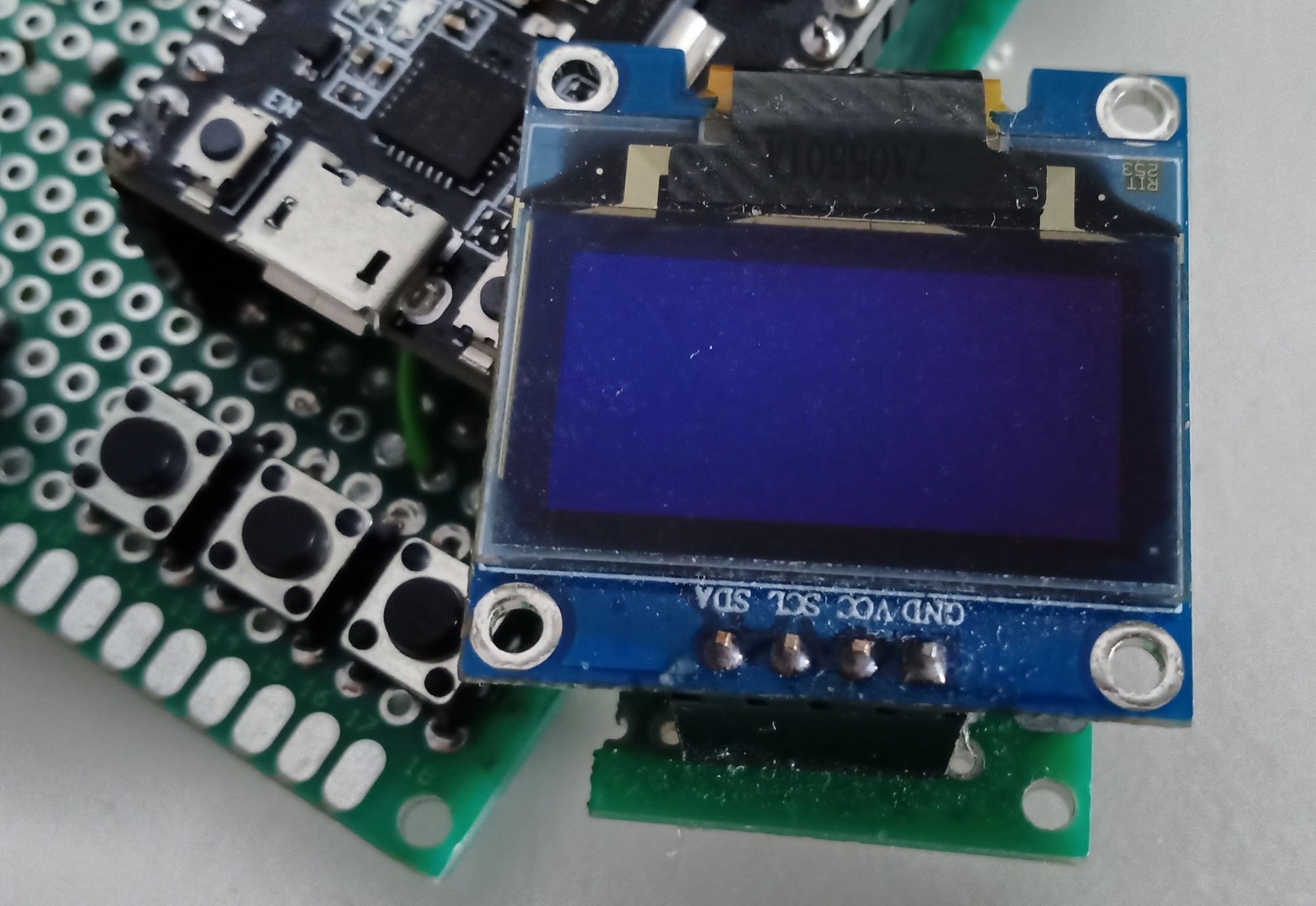
And that's why I added a small OLED display and three buttons.
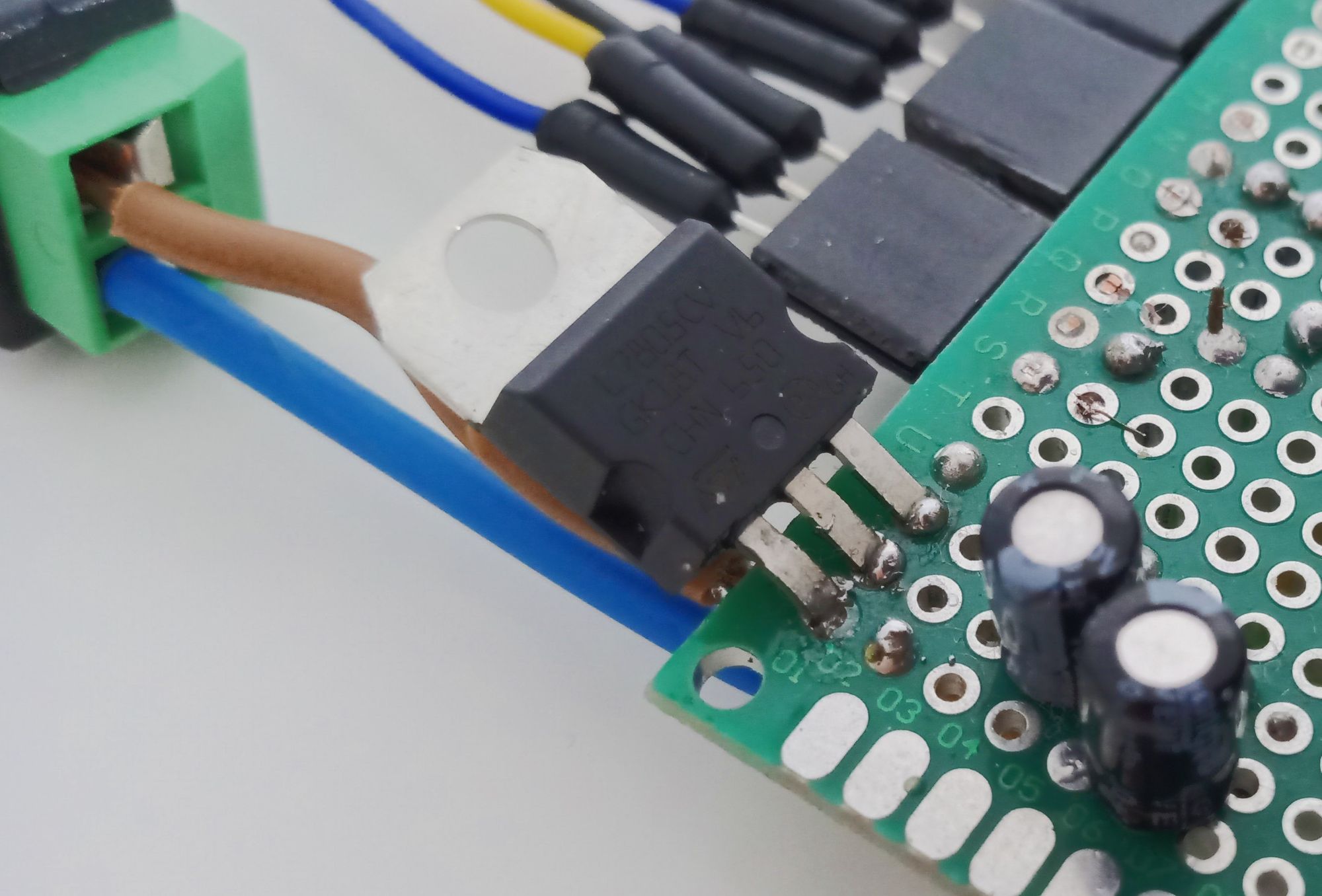
Not wanting to power the controller with two different voltages I added an L7805 voltage regulator as well. The devboard I used directly supports 5V so there was no need to get a regulator that outputs 3.3V. As with most voltage regulators, there is one capacitor added between the input and ground and one between output and ground to increase stability. In my case, they're both 100uF electrolytic ones.
Lastly, to actually control my RGBW strip running on 12V I opted for some IRFZ44N MOSFETs that would allow me to switch the 12V using the 3.3V of the ESP32.
Additionally, there will be a 1k resistor between the gate of the MOSFET and the pin of the ESP to dampen unwanted oscillation.
That means in terms of electronic components, minus cables and connectors, we got:
- 1 x ESP32 devboard (amazon affiliate link)
- 1 x L7805 voltage regulator
- 2 x 100uF electrolytic capacitors
- 4 x IRFZ44N MOSFETs
- 4 x 1k resistors
- 1 x OLED display (amazon affiliate link)
- 3 x buttons
- 1 x RGBW strip (amazon affiliate link)

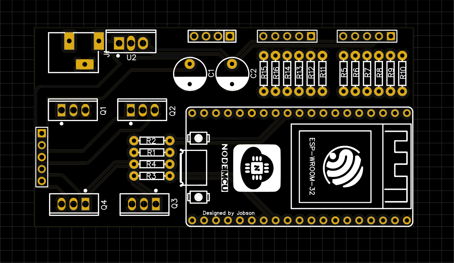
To the lower left, we got the 12V power jack as well as the connector for the display, in the center at the top we got the voltage regulator that takes in the 12V and converts it to 5V for the microcontroller.
To the right, we got the three buttons at the top and the four MOSFETs at the bottom.
And last but not least: that giant thing in the upper left corner is the devboard, unsurprisingly.
3.2 The perfboard prototype
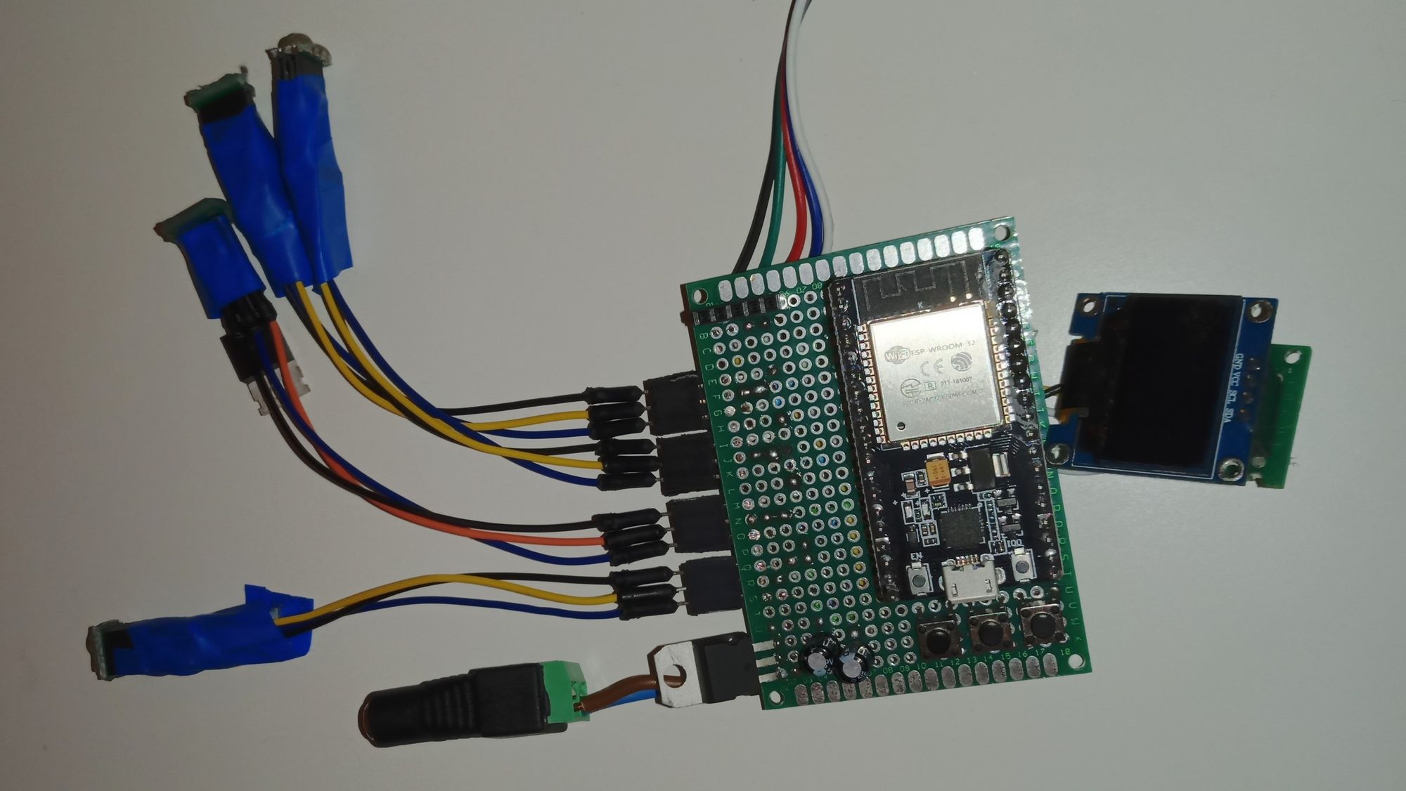
This horrendous looking thing is the cobbled-together version of my initial idea of a simple RGBW controller to which I later added the display and buttons, as well as a cable for one of the internal touch sensors of the ESP that I later removed.
The stuff I fucked up:
- Wired the MOSFETs the wrong way and had to cheat to get them connected the right way
- Did not use any of the internal resistors you can activate from code(pulling down the buttons in this case)
- Tried to use an input-only pin for PWM output, had to rewire a fair bit
- The display is directly connected to the headers from below with some thin wires and is therefore easy to rip off accidentally
3.3 First PCB prototype
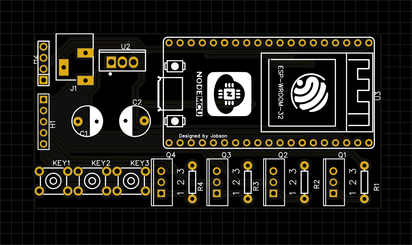
After finishing the prototype and the first iteration of the codebase I started to create an actual PCB design, trying to fix some of the issues mentioned above and get something better looking.
Yet I still made some mistakes, given my inexperience with designing PCBs or even designing circuits for that matter:
- Placing the MOSFETs in the lower right made them quite hard to route
- Why is the SPI connector to the left of the power jack?
- 12V wires are to thin to support the RGBW strip at its max current draw
- Lacking any kind of meaningful labels
4. The actual coding
4.1 Designing the interface
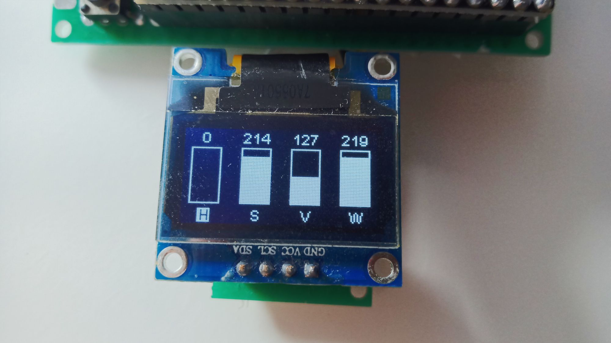
Designing the interface was actually quite a lot of fun. Having such a limited amount of pixels that you could, in fact, count them, but enough to not have to work that abstractly made it a manageable task.
The library I was using to control the display had some nice helper functions that made my life a lot easier. So I used my math skills to create a simple formula that could, given some amounts and spacing information, return the distance between two elements.
This allowed me to dynamically set the number of sections I wanted and place elements accordingly. And while my original idea to use circles was technically working but, let's say.. not that pleasant to the eye in terms of symmetry, replacing them with some rectangular bars that fill up accordingly from the bottom worked even better.
4.2 Adding HSV
After cleaning up my code somewhat and separating it into manageable chunks I started to add some more features.
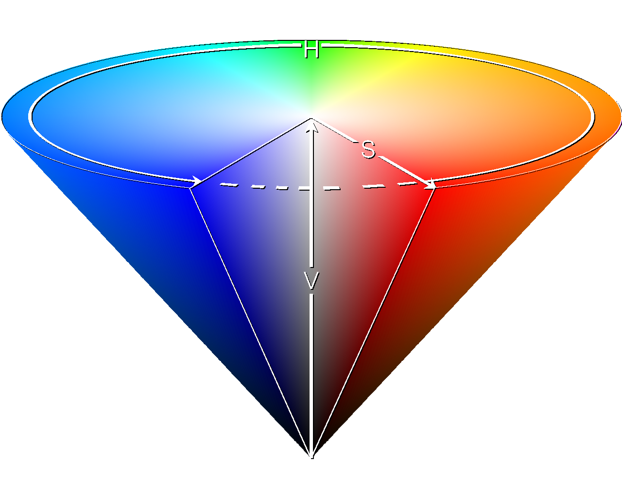
To make it easier to select a specific color without having to know its RGB components and without needing to try too many times, I chose to add a second color model called HSV that represents a given color by its Hue, Saturation, and Value.
Hue is the actual color of the light.
Saturation is the amount of white mixed into the light.
Value adjusts the brightness of the light itself.
4.3 Calculating white color portion
To actually use the W in the RGBW strip we need to calculate how desaturated the color is and use that to set the amount of white. If you want some more in-depth explanation check out my other post.
But the simplest way to do this is just to get the smallest of the RGB values, set white to that and set the original value to zero.
You might have been able to see from the picture of the display above that I kept the ability to set a value for W. It now controls how much white of the RGB spectrum is converted to the white LED. 0(or 0.0) is no conversion and 255(or 1.0) is a full conversion.
4.4 Adding some unit tests
To catch some problems early on I followed my own advice and started adding some unit tests. They are currently only there to test that I didn't fuck up the color conversions but will be extended to other parts of the code in the future.
As I extracted the color code into its own library I can now test it natively without having a board to test it on lying around.
5. Conclusion and a look into the future
5.1 Conclusion
The process of creating the controller as well as playing around with the LEDs was a lot of fun that I want to continue with in the future.
And after transforming my spaghetti code into more manageable chunks and writing some actual unit tests working with the code became a lot easier and makes it actually extendable for features that I want to add in the future.
I learned a fair bit about color regarding the RGB color space as well as color mixing in general and how to use my white LED. More about that here.
In addition to that, I started to get better at working with microcontrollers in general and how to handle them. More about that here.
All in all a very enjoyable process.. not that I thought that while working at the project.. that consisted of a lot more swearing.
But as I do not want to stop the project yet, here is a look into the future:
5.2 Design a better board
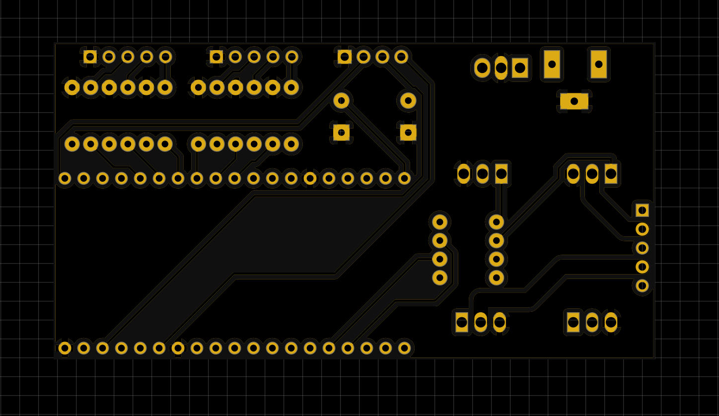
Before I get some actual PCBs I want to clean a few things up and change some of the control elements. This is the second version of the design that also supports longer strips without melting the traces as well as some rotary encoders instead of the hard to control buttons.
This is the version of the board that I actually want to get professionally made. There might be one or two things that will change before that happens but it's the general idea.
Changes:
- Replaced buttons with two rotary encoders
- Adjusted trace width for the 12V wires(2mm width, 0.6mm clearance)
- Moved MOSFETs closer to the connector
Criticism:
- Still missing labels for the connectors
5.3 Continue working on the controller firmware
I'm working on a better way to control the connected display with some more "high-level" functions. In the future, I want to be able to add and remove different displays with ease and switch between them.
I also want to add support for RGB+CCT(that are strips with two different white LEDs) as well as strips with individually addressable LEDs.
That would mean that I have to add one more MOSFET for the extra white LED and expose some additional data pins for the data lines of the individually addressable LEDs.
To make the actual color experience even better I want to increase the resolution of the PWM used to dim the different colors from 8-bits to 16-bits.
That would allow for far smoother transitions as well as some leeway to add actual color correction without it looking choppy. If you want to learn more about that, check out this blog post by saikoled.